

Solar Module Assembly: Automation for cell string interconnection soldering
Share


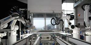
Solar cells are the heart of crystalline silicon solar panels. After stringing cells together, the strings must be interconnected to complete the circuit, carrying power to the junction box and beyond. The step of soldering the ends of the stringing ribbons to the cross-connection ribbons is a classic case for automation: it’s critical to quality, highly repetitive, and a chance to optimize efficiency and lower costs.
There are up to 150,000 solder joints in one megawatt (MW) of 240-watt panels. Automating this step provides reliability, improves yield and process stability, and enhances opportunities for data acquisition.
Module design considerations
The interconnection design of a module has important ramifications in the interconnection soldering step. Straight cross-connection ribbons can be handled and placed more quickly than those with L-bends. The additional steps of making the bend and soldering it also require supplemental equipment. Direct overlay of one cross-connection ribbon over another complicates the automation process, necessitating more material for the insulation between ribbons.
Straight connections have an added benefit in that they can facilitate a method of attaching the J-box without pulling the leads through the backsheet. Of course, soldering materials and fluxes must be carefully chosen to be compatible with the other materials in the module and, most importantly, with the encapsulating material.
Induction soldering
Automated interconnection work cells are designed according to a required cycle time. Faster cycle times are accomplished using additional handling and/or soldering systems, or by using a different soldering method. The most widely used method is induction soldering, which draws on high-frequency alternating current to produce resistance heating in the parts being soldered. A ceramic standoff is employed to press the stringing ribbon into contact with the cross-connection ribbon, and then the coil inside is energized to produce the heat and perform the joining. A camera system identifies joint location and verifies the correct position of the ribbons, providing information to the robot to perform the soldering.
Each of the induction soldering systems consist of handling robots to draw, cut, position, and hold the cross-connection ribbons in place, as well as the soldering robots that move the soldering heads (which may have two or three soldering fingers, according to speed required and number of bus bars on the strings). The handling robots have the added task of placing a protective Teflon strip under the joints to protect the encapsulant material, and removing the strip after the soldering is complete.
Faster cycle times are achieved by putting in more handling equipment and soldering equipment. The handling of the L-bending process can be made somewhat faster by adding handling systems.
Here are some representative cycle times on typical c-Si lines using induction soldering systems:
Cycle Time Item 1 (2 handling, 2 soldering robots):
75 Seconds / Module (with L-interconnection) | 60 Seconds / Module (with straight intercon)
75 Seconds / Module (with L-interconnection) | 60 Seconds / Module (with straight intercon)
Cycle Time Item 2 (2 handling, 1 soldering robot):
90 Seconds / Module (with L-interconnection) | 75 Seconds / Module (with straight intercon)
90 Seconds / Module (with L-interconnection) | 75 Seconds / Module (with straight intercon)
Cycle Time Item 3 (1 handling, 1 soldering robot):
200 Seconds / Module (with L-interconnection) | 180 Seconds / Module (with straight intercon)
200 Seconds / Module (with L-interconnection) | 180 Seconds / Module (with straight intercon)
Laser soldering
Laser soldering is a well-established technique for joining string interconnections, currently in use in many factories worldwide. By using two laser handling robots, speeds of under 40 seconds can be achieved. The heat input can be controlled so precisely that no Teflon protective strip is required, and the soldering can take place directly on top of the encapsulant. The parameters of each solder joint can be recorded for process and quality control. An added point of flexibility is that the lasers are particularly well suited for dealing with thinner cells.
The process flow in a line with laser soldering is changed to place the cross-connection ribbons prior to string matrix layup. Since the joints can be soldered directly on the encapsulant, the ends of the stringing ribbons can be laid on top of the cross connection ribbons. There’s no need to bend the ends of the stringing ribbons upward to slip the Teflon strips and cross-connection ribbons in after string layup.
Semi-automated soldering
Cycle times around 60 seconds can be reached (depending on interconnection design) using a semi-automated system, which combines manual placement of the cross-connection ribbons (utilizing special tooling) and automated soldering. This system derives the benefits of repeatability and reliability in soldering the joints, while reducing the initial investment in capital equipment.
Conclusion
Automated soldering can be a highly reliable and repeatable process. It can improve quality substantially, while reducing labor and rework costs. Return on investment in the initial capital equipment can be realized through higher efficiency, reduced rework, and higher overall product quality. Next to the cell stringing and string matrix layup process steps, automating interconnection soldering can have the most profound positive effects on the quality of the solar module assembly line, and should be considered for quality, as well as for cost-per-watt unit price reasons.
Gard Van Antwerp is the solar product manager for Reis Robotics USA.
Reis Robotics USA
www.reisroboticsusa.com
Author: Gard Van Antwerp
Volume: May/June 2012