


Improving on Collector Circuit TOV Mitigation by using combined circuit breakers & grounding switches
Share


Temporary Overvoltage (TOV) poses a serious hazard to equipment connected to a power grid. TOV can occur during a ground fault such as a tree limb falling on a power line. There are situations that can occur in wind plants that produce far more severe TOV than is normally encountered in typical MV utility distribution systems. These TOVs are a critical factor in wind plant insulation coordination.
Ground faults and loss of ground reference
In a three-phase effectively grounded system, a ground fault on one phase will cause the un-faulted phases voltage to rise if the X0/X1 ratio at the fault location is greater than one. Typical practice is to provide effective grounding (X0/X1 < +3) within the collector system. In most cases, neither wind turbine generators, nor the GSU transformers, provide neutral grounding for the wind plant MV system. The normal source of grounding for the collector feeders is from the wind plant substation. If a ground fault should happen, a derived neutral shift will occur as the substation breaker is tripped in response to the fault. While the wind turbine generators continue to operate the feeder becomes isolated without a ground source but with one phase connected to ground. As a result, the phase-to-phase voltage is maintained even when one of the phases is at zero potential to ground. For the unfaulted phases, the phase-to ground voltage and therefore the phase-to-neutral voltage can be the same value as the phase-to-phase voltage. In other words the unfaulted phase voltages will rise greatly, typically to 1.73 times pre-fault voltage or more as shown in (Figure 1).

The probability that the wind turbines will not trip in response to the fault, but keep operating, is greatly enhanced by low-voltage ride through (LVRT) compliance requirements that have been imposed on wind plants by grid operators. In fact the actual TOV can be significantly more severe than the 173% value, due to the capacitance of the isolated feeder. The “ungrounded” feeder is not actually ungrounded, but is grounded via the capacitance of the feeder cables. The negative reactance of the capacitance results in a negative X0/X1 ratio, which will further increase unfaulted phase voltage. Another consequence of the “capacitive grounding” of a nominally ungrounded feeder is the fact that the fault arc can clear itself, due to the very low fault current present once the feeder is isolated (some turbines might not trip on the fault), and then restrike. The restrike triggers a voltage oscillation and the arc may again interrupt at a current zero, trapping an even higher voltage. This process can repeat, escalating the voltage to higher levels.
 TOV mitigation
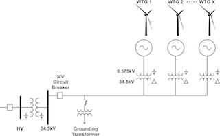
To avoid these TOVs, dedicated grounding transformers on each feeder (Figure 2) have become a common practice for wind farm collection circuit design. This eliminates the possibility of ungrounded operation due to feeder isolation.
The sizing of the grounding transformers must consider the rating of the wind turbine generators (WTGs) connected to the feeder, the WTG characteristics, and the amount of cable charging capacitance. In some cases, the WTG behavior for such a feeder isolation condition is complex enough to preclude simple calculation of grounding transformer impedance requirements. In such a case, detailed simulations are necessary. Without grounding reference, overvoltage can damage collector system cables, arrestors, and the wind turbine transformer. But, installing a grounding transformer on every feeder will increase equipment, labor, engineering, and installation costs, as well as the substation’s footprint.
 Improving TOV mitigation
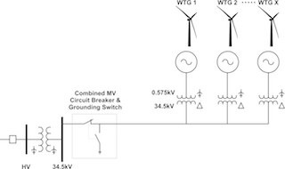
There is an improved alternate method to provide proper ground reference to a wind collector feeder not having to add a grounding transformer. It is to replace the substation vacuum circuit breaker with a combined vacuum circuit breaker and mechanically interlocked grounding switch (Figure 3). In essence, a high speed triple pole double throw switch with a very fast commutation time. The combined vacuum circuit breaker and mechanically interlocked grounding switch is a unique piece of equipment, especially designed for renewable energy collection circuit application. Once the collector circuit breaker opens on a single-phase-to-ground fault and the arc has been cleared, the mechanically interlocked grounding switch will close clamping all three phases to ground. As a result all WTGs will trip preventing higher temporary overvoltage values from developing
For comparison purposes, a temporary overvoltage was simulated three ways.
- Without any grounding reference;
- With a conventional breaker with a 1000 kVA wye-delta grounding transformer; and
- With a combined vacuum circuit breaker and mechanically interlocked grounding switch, in the collector circuit.
For all three simulated scenarios, a single-phase-to-ground fault is applied to phase A, and then the collector feeder is tripped. The wind turbine generators continue to operate while the feeder becomes isolated (Figure 4). Without a ground reference but with one phase connected to ground, the unfaulted phase B voltage (Red Trace) rise well over the typical 1.82 per unit temporary overvoltage capability of a surge arrester (Pink Trace).
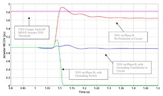
The (Blue Trace) shows the transient and temporary overvoltage on Phase B with a conventional breaker and a grounding transformer in the circuit. When the substation circuit breaker is replaced by a combined circuit breaker and mechanically interlocked grounding switch, the voltage on Phase B (Green Trace) rise to about 1.15 p.u. and then drops to zero. Both grounding methods are effective in limiting the temporary overvoltage. However, the overall system stress and absorbed energy by the surge arrestors will be further reduced by the combined circuit breaker and mechanically interlocked grounding switch. As an added bonus, a grounding breaker will also mitigate overvoltage caused by a high generation to load ratio event. Load rejection, occurs when a significant portion of the load becomes separated from the generation source. E.g. If a high voltage breaker trips at the point of interconnection, the wind generating plant will be islanded. The remaining connected load will be the wind farm itself which is much lower than the output of the system and a voltage rise can occur. When the substation high voltage breaker opens all feeder breakers will trip clamping each and every feeder to ground preventing a possible overvoltage. Installing a grounding breaker on every feeder will reduce equipment, risk of environmental issues (transformer oil spills, fire), labor, engineering, and installation costs, as well as the substation’s footprint.
Conclusion
Combined circuit breakers and mechanically interlocked grounding switches are an emerging alternative to grounding transformers. The industry is steadily increasing the use of grounding breakers in wind plant collector systems with positive results. By eliminating grounding transformers’ high costs and core losses, grounding breakers provide significant up-front and long-term savings, while increasing system efficiency and reliability.
Carlos Ober is an international sales executive and applications engineer at EMA Electromechanics
EMA Electromechanics | www.emaelectromechanics.com
SOURCES & REFERENCES
- Steven W. Saylors, P.E., “Large Wind Plant Collector Design “Wind Farm Collector System Grounding, IEEE PES Transmission and Distribution Conference 2008.
- Reigh. A. Walling, P.E., “Overvoltage Protection and Arrester Selection for Large Wind Plants” IEEE TD2008-000728
- IEEE Standard 142-1991: IEEE Recommended Practice for Grounding Industrial and Commercial Power Systems.
- Enernex “Comparison of the Technical and Economical aspects of the Combined 34.5 kV Vacuum Circuit breaker & High Speed Grounding Switch VDH/GSMI vs. grounding Transformers” 2013
- Advance Energy “Neutral Connections and Effective Grounding” white paper
Volume: July/August 2015